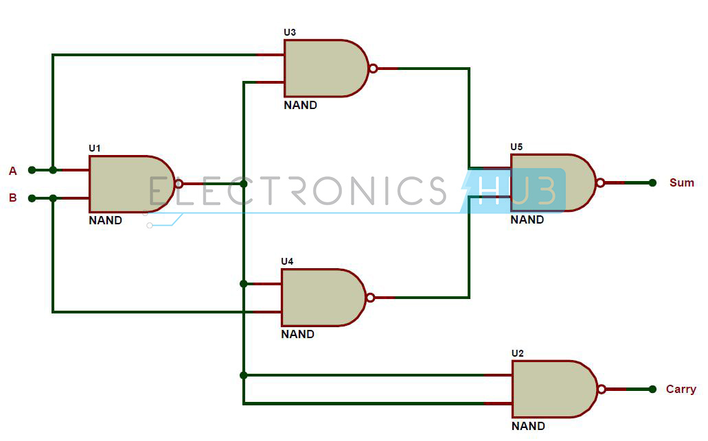
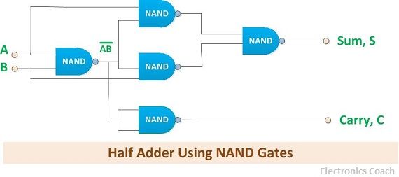
circuit diagram of half adder using nand gate
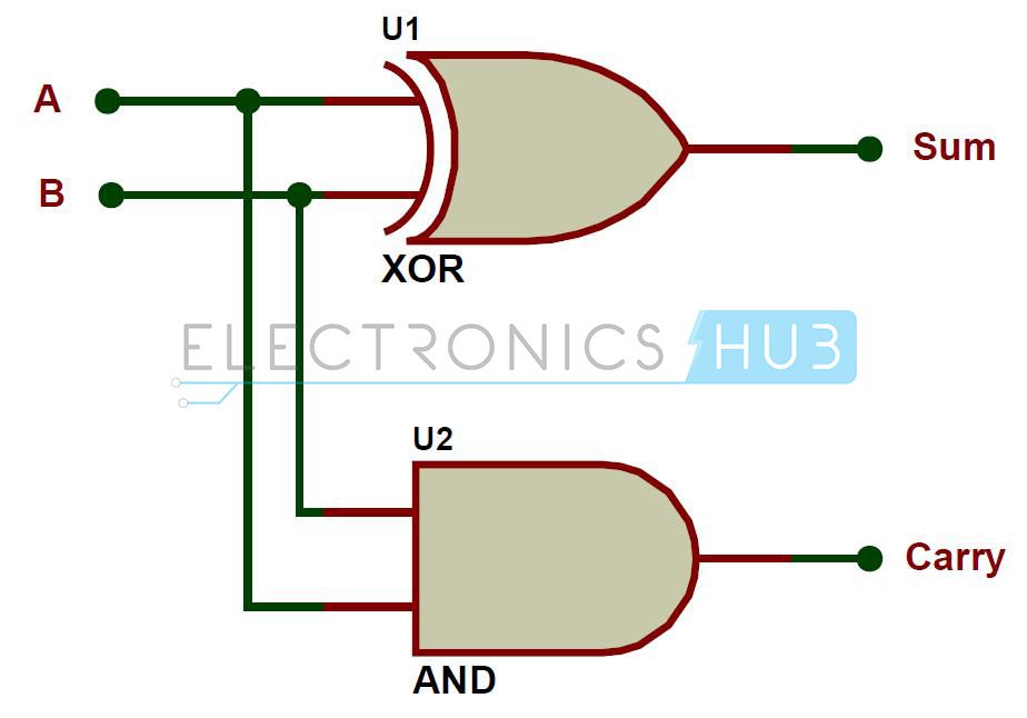
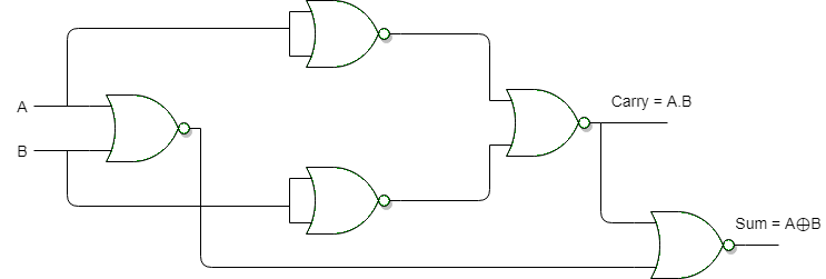
A full adder circuit uses 7486 XOR IC 7408 AND IC and 7432 OR IC all the three ICs are the two-input logic gates. A digital electronic circuit that functions to perform the addition on the binary numbers is defined as Half Adder.
Half Adder Circuit And Full Adder Circuit Using Nand Gates
The half adder circuit is built using XOR gate IC 7486 and logic AND gate IC and both.

. HALF ADDER USING MUX Show circuit diagram. Half Adder Truth Table 00 0 01 1 10 1 11 10 These are the least possible single-bit combinations. This is a demonstration of the half adder that I made using NAND gates.
Minimum NANDNOR Gates - Realization For ExORExNorAdderSubtractor gateoverflowin. The implementation of half adder. Draw the logic diagram.
But the result for 11 is 10 the. Combinational circuits using Decoder. Implementation of Half Adder using NAND gates.
Half Adder Using NAND Gates Procedure Place the IC on IC Trainer Kit. Half Adder Using Basic Gates Show circuit diagram. Implement the circuit as shown in the.
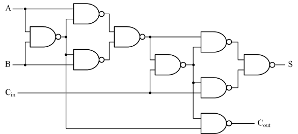
Draw K-maps using the above truth table and determine the simplified Boolean expressions- Also Read-Half Subtractor. Single-bit Full Adder circuit and. The circuit diagram can be found here.
This connections of a NAND gate shown below may be the most basic and works by using only 1 gate of a 7400. The A and B. Half Adder and Full Adder circuits is explained with their truth tables in this article.
The 5V DC supply is applied to the circuit. Draw the logic diagram. 1 NOT Gate from a NAND Gate When the input pins a of a.
Half adder using nand gates 0 Stars 320 Views Author. The implementation of half adder. Feb 01 2020 Updated.
11 circuit diagram of half adder using nand gate Saturday October 22 2022 It takes binary bits as input and produces a two-bit binary result by adding them. The process of addition is denary the sole difference is the. Draw K-maps using the above truth table and determine the simplified Boolean expressions- Also Read-Half Subtractor.
Nand subtractor gates nor adder half using minimum exor gate realization. 9 rows The 2-bit half adder truth table is as below. Design of Full Adder using Half Adder circuit is also shown.
Half adder circuit is built using the two ICs 7486 7408 combined together. Apr 07 2021 Add members. Connect VCC and ground to respective pins of IC Trainer Kit.
Multiplexers in Digital Logic.
Digital Logic Minimum Nand Nor Gates Realization For Exor Exnor Adder Subtractor
Half Adder Circuit And Full Adder Circuit Using Nand Gates
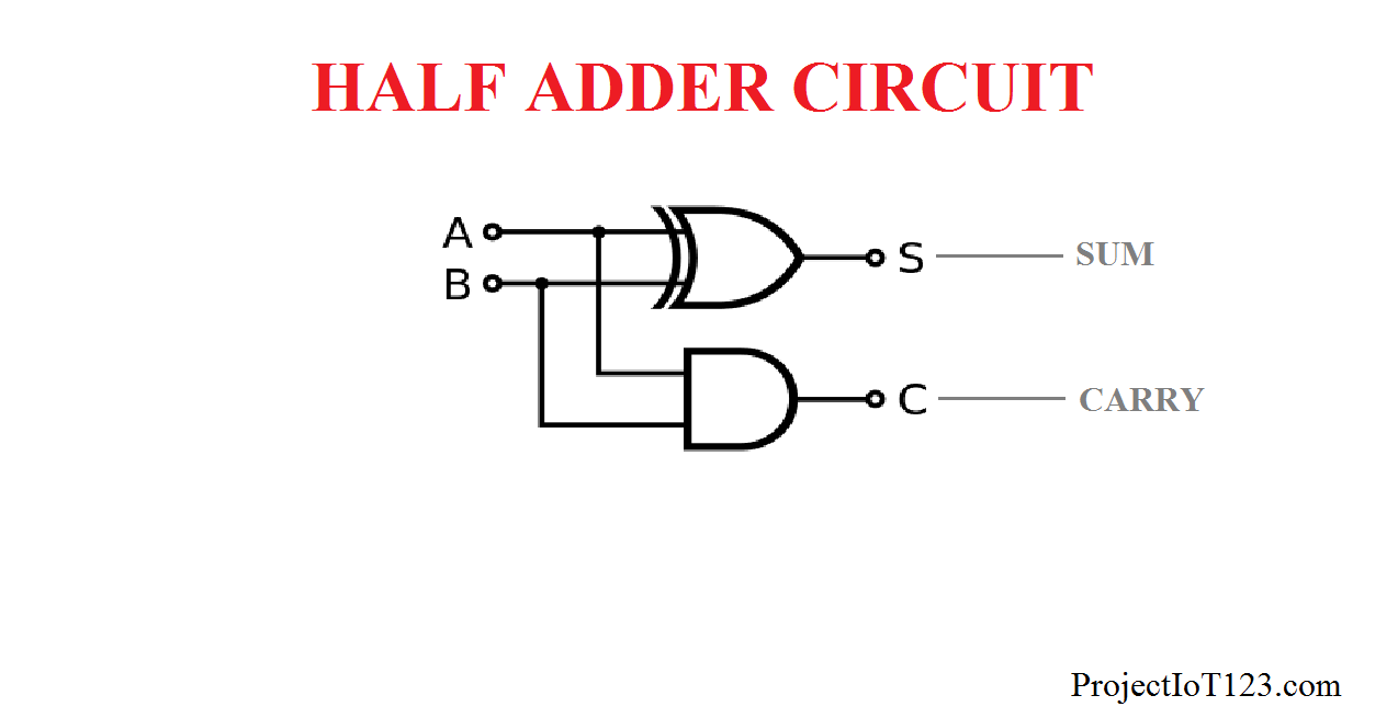
Introduction To Half Adder Projectiot123 Technology Information Website Worldwide
Digital Electronics Laboratory

Logic Gates Go For A
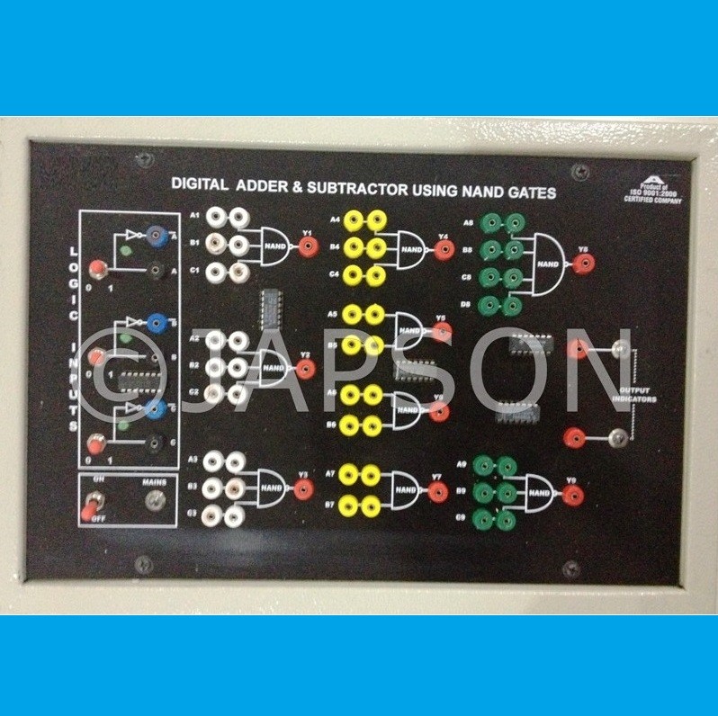
Digital Trainer To Verify Adder Subtractor Using Nand Gate Experiment Apparatus
What Is Half Adder Half Adder Using Nand Gates Nor Gates Truth Table Electronics Coach

Half Adder Using Nand Gate Tinkercad
Virtual Labs

Half Adder Using Nand Gate Multisim Live

Half Adder Using Nand Gates Youtube

Half Adder Design Using Universal Gates Youtube
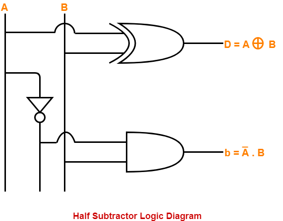
Half Subtractor Using Nand Gates Gate Vidyalay
Digital Logic Minimum Nand Nor Gates Realization For Exor Exnor Adder Subtractor

Implimentation Of Half Adder Using Nand Gate ह न द Youtube

Creating A Full Adder Circuit Using Nand Gates Eeweb
Half Adder Circuit And Full Adder Circuit Using Nand Gates